Spandrel Glass Explained Can Be Fun For Everyone
Table of ContentsSpandrel Glass Door for BeginnersHow Spandrel Glass Detail Dwg can Save You Time, Stress, and Money.The 20-Second Trick For Spandrel Glass Description
The masonry layout of the non-participating infill is performed based on the suitable MSJC Code areas for reinforced or unreinforced masonry(Section 3. 2 for unreinforced infill as well as Section 3. MSJC Code Area B. 3. 5 helps the designer figure out the suitable augmented lots for developing the bounding framework participants. spandrel glass exterior. Structure members in bays beside an infill, yet not in call with the infill, ought to be designed for no much less than the pressures (shear, moment, and also axial)from the equal strut structure analysis. The shear and also moment put on the bounding column has to go to least the arise from the equal strut structure evaluation multiplied by an element of 1. 1. The axial lots are not to be much less than the results of that analysis. Additionally, the horizontal component of the pressure in the equivalent strut is included to the style shear for the bounding column. 1, as well as the axial loads are not to be much less than the outcomes of that analysis. The vertical part of the force in the equal strut is included in the style shear for the bounding beam of light or piece. The bounding framework design need to also consider the volumetric adjustments in the masonry infill product that may take place in time because of regular temperature level and dampness variations. 2 m)apart along the border of the infill. Figure 2 shows an instance of a mechanical connector made up of clip angles welded to the lower flange of the steel beam.Connectors for both taking part and non-participating infills are not allowed to move in-plane lots from the bounding structure to the infill. Research study(ref. 3 )has shown that when ports transmit in-plane lots they produce areas of local anxiety and can cause early damage to the infill. This damages after that lowers the infill's out-of-plane ability because arching action is hindered. EXAMPLE 1: STYLE OF TAKING PARTframe to prevent the unintended transfer of in-plane loads from the frame into the infill. The MSJC Code needs taking part infills to fully infill the bounding structure and also have no openingspartial infills or infills with openings might not be taken into consideration as component of the side force resisting system since structures with partial infills have actually normally not performed well throughout seismic events. 2 )in the late 60s, is the characteristic tightness specification for the infill as well as offers a measure of the loved one rigidity use this link of the structure as well as the
infill.
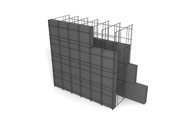
STONEWORK INFILL WALL SURFACE FOR IN-PLANE PLENTIES Take into consideration the straightforward structure of Number 3. Steel structures sustain all gravity loads and the lateral lots in the east-west direction. The bounding columns are W10x45s oriented with the solid axis in the east-west direction. The bounding beams over the masonry infill are W10x39s. The stonework infill stands up to the lateral tons in the north-south direction. Usage nominal 8-in. =24.
STONEWORK INFILL WALL FOR IN-PLANE PLENTIES Think about the simple structure of Number 3. Steel structures support all gravity loads and also the lateral lots in the east-west direction. The bounding columns are W10x45s oriented with the solid axis in the east-west direction. The bounding beams above the stonework infill are W10x39s. The masonry infill withstands the lateral lots in the north-south instructions. Use small 8-in. =24.
The smart Trick of Spandrel Glass Film That Nobody is Discussing

MASONRY INFILL WALL SURFACE FOR IN-PLANE PLENTIES Think about the simple framework of Figure 3. Steel structures sustain all gravity tons as well as the lateral lots in the east-west direction. The bounding columns are W10x45s oriented with the strong axis in the east-west instructions. The bounding beam of lights over the stonework infill are W10x39s. The stonework infill resists the lateral tons in the north-south instructions. Usage nominal 8-in. =24.
MASONRY INFILL WALL FOR IN-PLANE PLENTIES Consider the easy framework of Figure 3. Steel structures sustain all gravity tons as well as the lateral tons in the east-west instructions. The bounding columns are W10x45s oriented with the strong axis in the east-west instructions. The bounding light beams above the stonework infill are W10x39s. The stonework infill stands up to the lateral load in the north-south instructions. Usage small 8-in. =24.
Spandrel Panels Definition Can Be Fun For Everyone
STONEWORK INFILL WALL FOR IN-PLANE PLENTIES Take into consideration the basic structure of Number 3. Steel structures sustain all gravity loads as well as the lateral tons in the east-west direction. The bounding columns are W10x45s oriented with the strong axis in the east-west direction. The bounding beams over the stonework infill are W10x39s. The masonry infill over at this website stands up to the side lots in the north-south instructions. Use nominal 8-in. spandrel glass en español. =24.

STONEWORK INFILL WALL SURFACE FOR IN-PLANE LOADS Take into consideration the basic structure of Figure 3. Steel structures sustain all gravity tons as well as the lateral load in the east-west instructions. The bounding columns are W10x45s oriented with the strong axis in the east-west direction. The bounding light beams over the stonework infill are W10x39s. The stonework infill resists the lateral tons in the north-south instructions. Usage nominal 8-in. =24.
MASONRY INFILL WALL SURFACE FOR IN-PLANE PLENTIES Consider the easy framework of Number 3. Steel frames support all gravity tons and the side load in the east-west direction. The bounding columns are W10x45s oriented with the solid axis in the east-west direction. The bounding beams above the masonry infill are W10x39s. The masonry infill withstands the side load in the north-south instructions. Usage small 8-in. =24.